Projects
“Make it Talk“
For this project, I built a small system using an ESP32 microcontroller, a TK17 impact switch, a TK01 LED, and the LightBlue Bluetooth app. The goal was to make a physical object sense something in the real world and then “talk” by responding through both a visual signal and a wireless message. I wired the impact switch to the ESP32 so that when it was hit, the board would detect the vibration and immediately turn on the LED. This gave me a simple way to see the input being triggered.
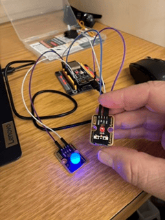
After I got the physical response working, I added Bluetooth communication so the ESP32 could send a message to my phone. Using the LightBlue app, I set up a characteristic that the ESP32 could write to whenever the switch was activated. Once everything was connected, hitting the impact switch caused the LED to light up and sent a notification straight to my phone. This showed how a basic sensor input can turn into both a machine‑to‑machine and human‑machine interaction. It also demonstrated how microcontrollers can bridge physical events with wireless communication, which is the main idea behind the “Make It Talk” assignment.
“make it smart ” sensing and responding
Building a smart physical system starts with giving an object the ability to sense something in the real world and then respond to it. In this project, I used the Lonely Binary TK17 collision sensor as the input and the TK01 LED as the output. The ESP32 acted as the main platform, functioning like a programmable breadboard where all the components connected. After wiring the sensor’s VCC, GND, and OUT pins to the ESP32 and attaching the LED to GPIO 5 and ground, I installed the Arduino IDE and uploaded a program that reads the sensor’s digital signal. When the TK17 detects an impact, it sends a HIGH signal to the ESP32, which responds by blinking the LED in one‑second intervals. This creates a complete sense‑and‑respond loop: the sensor detects a physical event, the microcontroller interprets it, and the LED reacts.
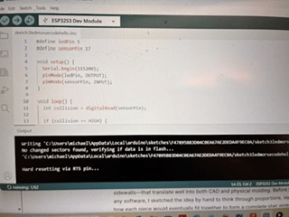
Putting everything together required both hardware setup and software understanding. I connected the wires on the ESP32, assigned the correct pins in code, and tested the program through the Arduino IDE. AI played a good‑sized role in helping me understand the logic, fix syntax errors, and structure the program so it worked the way I wanted. I plan to use AI even more as my designs become more complex, especially when I start working with additional sensors, motors, and more advanced control logic. This was a great project because now the possibilities feel endless with what can be done using these kits — each new component opens the door to another smart behavior, reaction, or idea I can build.
casting and molding
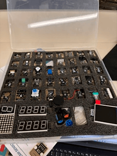
For this casting and molding project, I wanted to create something simple in shape but detailed enough to show the full workflow. I decided on a miniature staircase model because it includes multiple geometric features—risers, treads, stringers, and sidewalls—that translate well into both CAD and physical molding. Before touching any software, I sketched the idea by hand to think through proportions, layout, and how each piece would eventually fit together to form a complete stair assembly.
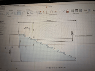
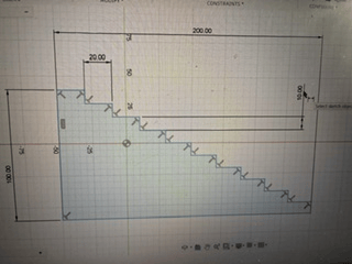
After the hand sketch, I moved into Fusion 360 to build a clean digital version of the staircase. I created individual sketches for the risers, base, and side stringers, making sure each part had accurate dimensions and proper alignment. Once the sketches were complete, I used extrude operations to turn them into solid bodies. Seeing the model come together digitally helped confirm that the geometry would create a workable mold once printed.
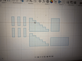
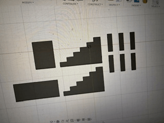
With the model finalized, I exported the components as an STL file and sent them to the 3D printer. The prints came out clean, and once all the pieces were finished, I assembled the stair form. I glued the parts together and reinforced the seams with tape to prevent leaks. This step was important because any gaps in the form would affect the final cast and create unwanted imperfections.
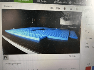
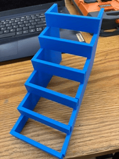
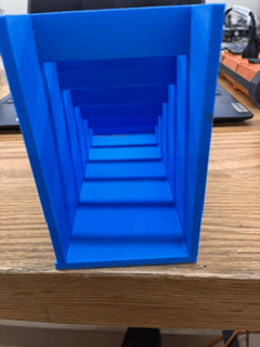
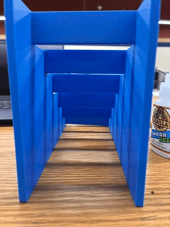
To create the actual cast, I mixed plaster powder with water until I reached a smooth, pourable consistency. I carefully filled the stair mold, making sure the mixture reached all the corners and edges. Once poured, I let the plaster set and harden. This waiting period is crucial because removing the cast too early can cause cracks or breakage.
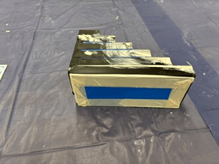
After the plaster fully cured, I removed the tape and separated the mold pieces. The cast staircase held its shape well and captured the details of the risers and stringers. Seeing the final form was a satisfying moment because it showed how each step—from sketching, to CAD, to printing, to casting—worked together to create a solid, physical model.
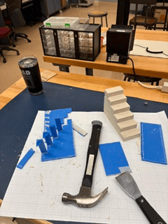
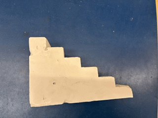
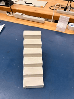
This project gave me hands‑on experience with the full casting and molding workflow. It reinforced how important it is to think ahead about tolerances, seams, and material behavior. Even though the staircase was a small model, the process mirrored real‑world construction and fabrication challenges. Overall, the project was engaging, and it helped me better understand how digital design translates into physical manufacturing.
L‑Bracket 3D Printing Evaluation
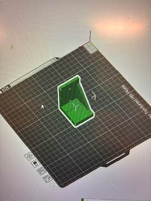
For this project, we were given an STL file of an L‑bracket with a gusset and asked to explore different ways it could be 3D printed. The goal was to understand how filament type, infill pattern, and print orientation affect the strength of a functional part—especially at the high‑stress inside corner where the two legs of the bracket meet.
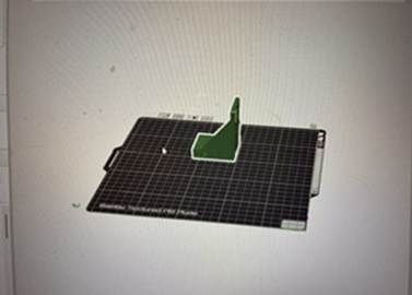
Filament Type
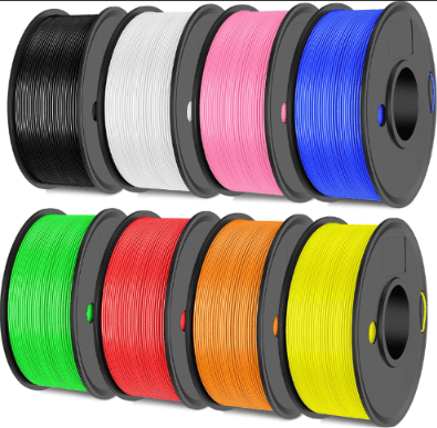
I printed the bracket using PLA, which is common for classroom and general prototyping because it is easy to print, dimensionally stable, and produces clean surfaces. PLA is stiff but brittle, so layer orientation plays a major role in preventing failure at the L‑joint. If printed in a weaker orientation, PLA tends to snap cleanly along layer lines. Stronger filaments like PETG or ABS could improve toughness, but PLA was sufficient for comparing print methods.
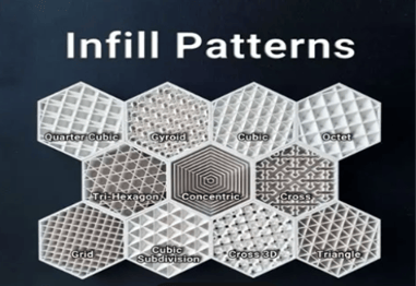
Infill Type & Density
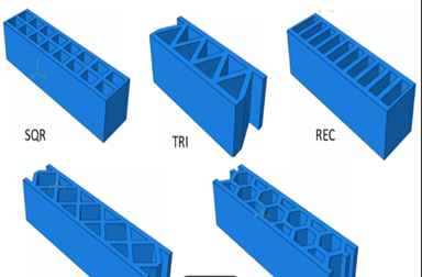
I tested a standard grid infill at 20–30%, which is typical for brackets that don’t need extreme load capacity. Grid infill provides balanced strength in multiple directions. In Bambu Studio, switching between infill types (grid, gyroid, cubic) showed how each pattern distributes internal support. Gyroid offered smoother stress distribution, but the biggest strength factor still came from orientation, not infill.
Print Orientation
Orientation had the largest impact on structural performance:
- Flat orientation (lying on its back) Layers run along the length of the bracket, making the L‑joint significantly stronger. The gusset also prints as a continuous diagonal, improving load transfer. This orientation required some support under the gusset but produced the strongest part.
- Vertical orientation (standing upright) Layers stack through the thickness of the bracket, meaning bending forces pull across the layers. This creates a weak point at the inside corner, and the bracket is more likely to fail along a clean layer line. From the original stl some lettering was not seated correctly on the bracket. This had the 3d print create supports to accommodate the symbols. At the end of the print the symbols peeled off when the supports were removed.
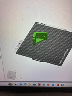
Previewing in Bambu Studio
Using Bambu Studio’s layer preview was essential for understanding how the bracket would behave under load. By scrubbing through the layers, I could see:
- how the gusset was built up layer by layer
- where infill connected (or didn’t connect) to the outer walls
- how the filament lines aligned with the direction of expected force
- Potential weak points where layers changed direction or created small gaps
The preview made it clear that printing the bracket flat created continuous filament paths through the L‑joint, while printing upright created stacked layers that could delaminate.
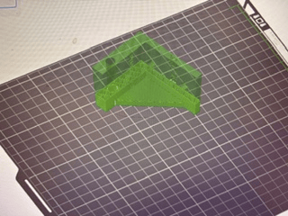
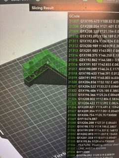
The 3D Print Itself
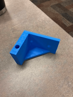
During the actual print, I paid close attention to how the bracket was being built layer by layer. Watching the preview in Bambu Studio helped me anticipate where supports would form, how the gusset would be reinforced, and how the outer walls bonded to the infill. Once printing began, I could see the filament lines forming the L‑joint and how well the gusset tied into the vertical and horizontal legs. The print quality was consistent, and the bracket came off the bed with clean edges and solid layer adhesion. Handling the finished part made it easy to compare how different orientations affected stiffness, flex, and potential failure points, especially around the inside corner where the bracket experiences the most stress.
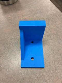
Conclusion
This project demonstrated how print settings directly affect the mechanical performance of a functional part. Filament type and infill matter, but orientation is the most critical factor for strength in an L‑bracket. Bambu Studio’s preview tools made it easy to visualize layer direction and predict failure points before printing. The 3d print came out surprisingly strong. I look forward to stress testing this in the lab with the other 3d prints.
SCAN AND PRINT IN OUR 132 MEC CLASS
In or class this week we used the 3d model scanner to scan a component fully and export the file to the 3d printer. we also used the mesh feature in fusion 360 to import, repair, edit and convert polygonal 3d models composed of triangles, quads and/or gons. this process allowed us to select an object and scan it and create a near perfect replica of the item. the scanning took some time to scan all the features of the toy i chose to scan and at the end some descripincies between the original and the copy.
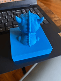
this is the 3d print version i did at home of the scanned dragon toy. I had to create plinth block because the 3d scan had problems filling in all the holes.
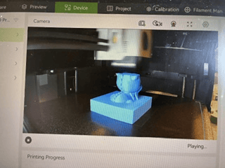
this is the 3d print in motion in the printer
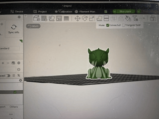
this is the exported/imported scan in bambu printer before it prints
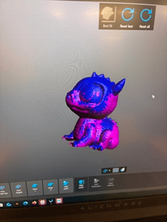
this the merged 3d scan, the scanning process had us scan the object upright and then turn it over and scan again to get all the areas mapped.
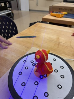
this the original toy being scanned on the scanning block. this block rotates in order to help scan all the areas of the object.
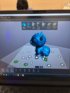
you can all the references dots in this picture. at the beginning of the scan, you calibrate the scanner/sensors so that the scanner knows where the object is when scanning it.
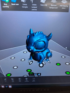
another point of reference for the scanner
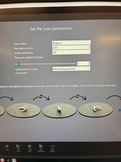
this is part of the setting up and calibration of the scanner.
2-D JIGSAW DESIGN IN FUSION AND CUT OUT ON LASER JET
In my mec 132 class we were tasked with making a jigsaw and laser cutting it out. This was a great project to utilize the skills I had learned from my cad class. The project entailed coming up with a design for a jigsaw and sketching it, then using fusion 360 to draw it. After that was finished, I created an stl file and sent it over to the laser printer so I could cut it out.
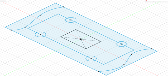
The picture above is the first design I came up with , I created this on fusion, made the file and then cut it out on the laser printer on a piece of paper.
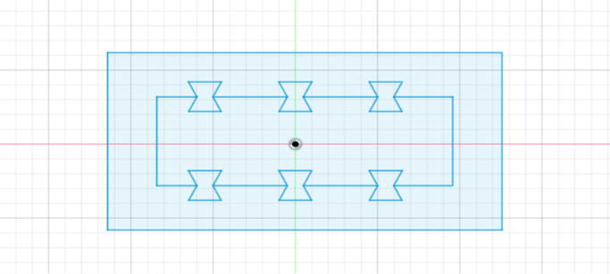
The next design I made using dovetails to create the jigsaw pieces was also done on fusion. When I laser cut out the pieces, I discovered an interesting issue. When the paper design was cut all the pieces fit together each time, no matter how many times the puzzle was scattered. With the dovetail design that was done on the wood the pieces were very difficult to fit back in. After further inspection I realized that the laser does not move on a gantry system like it does on a 3d printer. This meant when the laser cut out on the edges it cut the wood on an angle, this meant that each piece was not only able to fit in an individual spot despite them all being uniform in size and shape.
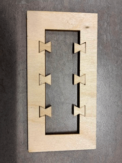
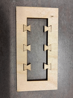
You can see in the picture above that the pieces do not fit nicely and are snug in the dovetail locations, this is because of the angle that the laser left on the pieces. I think the next time I will use thinner material or a laser cutter on a gantry system.
business card laser engraving
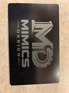
in this class we took our designs from a previous class and laser engraved the design onto a metal business card.
Arcade Cabinet Construction Project
Design • Build • Completion
Summary: This project was one of the most extensive hands‑on builds in my coursework, combining design, fabrication, electronics, woodworking, and problem‑solving into a full end‑to‑end arcade cabinet. The goal was to take a concept from initial sketches all the way through digital modeling, material selection, construction, assembly, wiring, and final finishing. It was a complete design‑to‑manufacture workflow — the kind of project that blends my construction background with my new training in mechatronics and design manufacturing.
The process began with planning the cabinet’s dimensions, ergonomics, and layout. I created digital models to visualize the structure, test proportions, and plan component placement. Once the design was finalized, I moved into fabrication: cutting panels, routing edges, assembling the frame, and reinforcing structural points. My construction experience played a major role here — accuracy, sequencing, and clean assembly were essential to getting the cabinet square, stable, and visually sharp.
The electronics portion added a new layer of complexity. I installed the display, controls, wiring harnesses, power management, and internal mounting brackets. This required careful routing, cable organization, and integration of multiple systems into a compact space. It was a great example of how mechanical design and electrical integration work together in real projects.
Finishing the cabinet involved sanding, painting, detailing, and final assembly. The completed build is fully functional, durable, and visually clean — a showcase piece that demonstrates both craftsmanship and technical capability.
This project represents the intersection of everything I’m working toward: construction skill, digital design, manufacturing processes, and practical problem‑solving.
Key Skills Used:
- Digital design and layout planning
- CAD modeling and dimensional visualization
- Woodworking, cutting, routing, and structural assembly
- Electronics installation and wiring integration
- Component mounting and internal system organization
- Finishing, detailing, and final assembly
- Full design‑to‑manufacture workflow
Outcome: A fully built, fully functional arcade cabinet that demonstrates advanced hands‑on construction ability, technical integration, and the ability to take a project from concept to completion. This build highlights how my construction background and new mechatronics/design manufacturing training work together to produce clean, practical, and well‑engineered results.
Section 3 – toolbox design and presentation
Overview
The purpose of the toolbox design and presentation project was for a team to work closely in a team to design, model and present a fully functional multi component toolbox. The project would make use utilize the skills that we had learned in the cad class to that point and also help us develop new skills like presenting to an audience and collaborating with a partner. We would use a variety of skills and abilities to complete the project, hand sketching, part modeling, assemblies, joint creation and constraints. Even though this project was for our cad class the main component for the class would be to create a PowerPoint and present it. The presentation would ensure that we created the project with good workflow and keep a clear path so that others could follow our work path all along following the instructions from the project definition.
These sketches helped me organize the dimensions and plan the modeling steps in Fusion 360. Originally we both split apart at the beginning of the project to start creating concepts individually. These are some of my hand sketches.
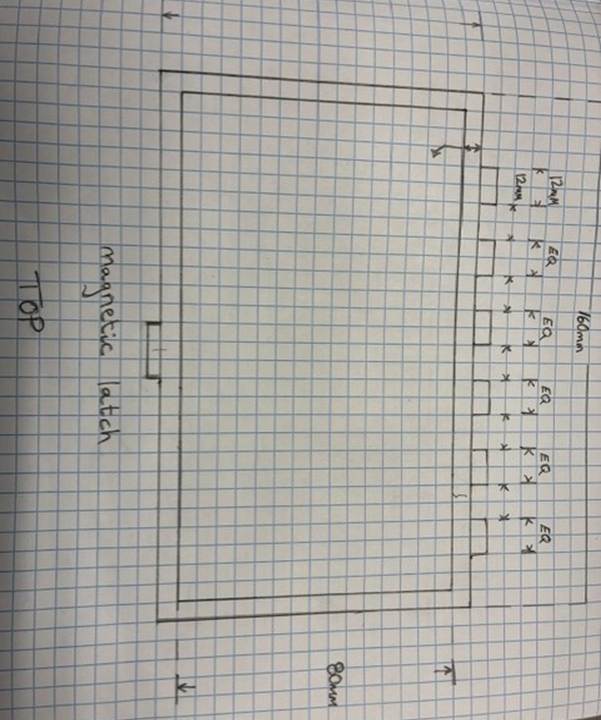
This is a top view of the bottom portion of the toolbox. I have the hinges and latch in the sketch.
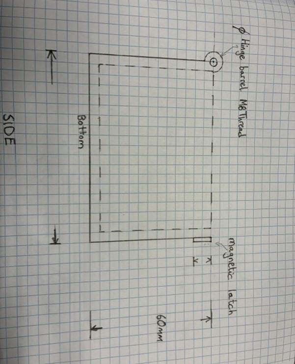
This is a side view of the lower portion of the toobox. We can see the hinges and latch.
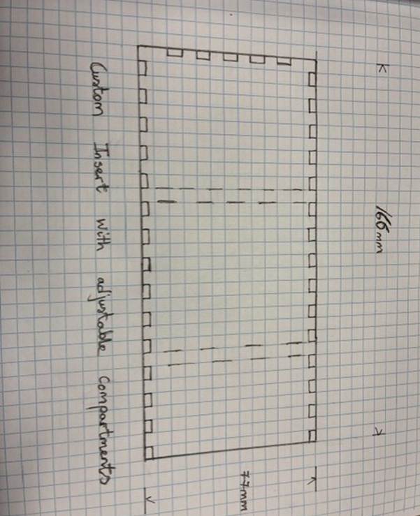
This is a top view of the adjustable compartment idea that I had during the design phase. This would allow someone to alter the inside walls of the toolbox to allow different size equipment.
Below you will find some of the 3d modeling in fusion for the conceptual ideas I had for the toolbox.
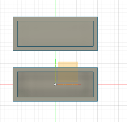
This is the start of the 3d modeling for the toolbox top and bottom lids.
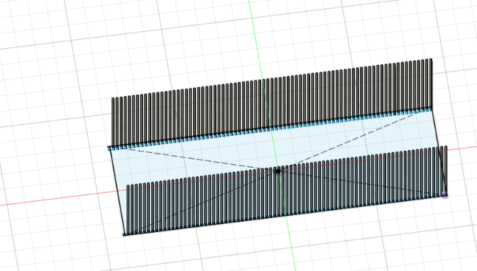
This is the start of the of the 3d modeling in fusion for the adjustable insert.
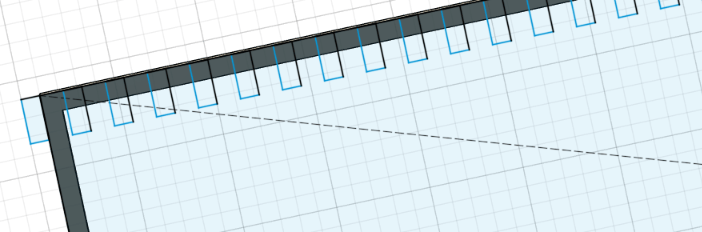
This is the rough 3d modeling for the insert of the toolbox.
PowerPoint Assembly and presentation
After my partner and I provided our individual concepts and sketches we began to brainstorm on a final design that we could work toward. We then started to create a fulkl set of documents for the presentation.
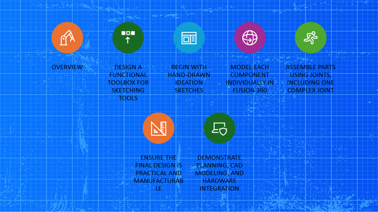
This is the overview slide of what we needed to provide for the project and a workflow path.
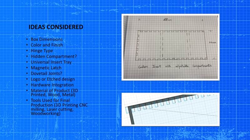
This slide talks about the ideas considered for the toolbox design. We considered multiple concepts and even tried to implement them.
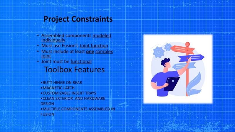
This slide shows us the constraints that we had to abide by. It also has some of the features
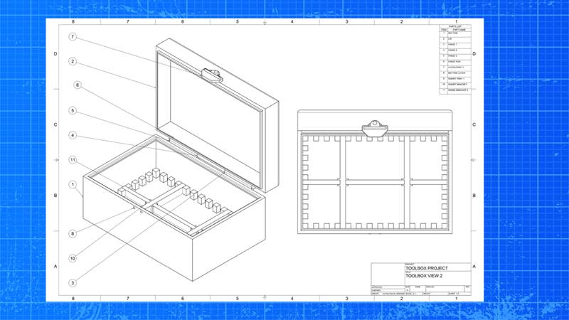
This slide has a schematic of the toolbox and gives the features listed and what they are.
Fusion 3d modeling
These are some of the 3d models that were created for the project. This gave everyone a clear idea of what the toolbox would look like. At some point I would like to 3d print the toolbox and figure out what the best method would be for creating one toolbox vs one hundred.
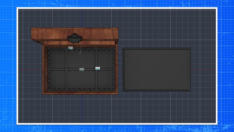
This a top view of the tool box with the custom adjustable insert.
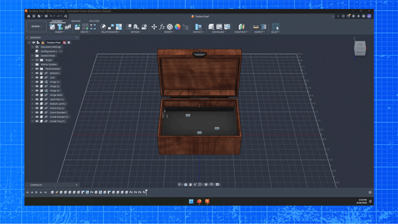
This slide from PowerPoint shows the 3d model and shows the way it is created.
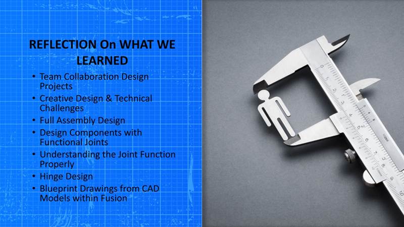
Here are some of the objectives and skills learned from this project and presentation.
One of my favorite parts of the project was the conceptual part that allows me to think outside the “box” pun intended. This is always my favorite portion of any project, giving myself time to think of different ways of creating or achieving a goal.
Residential Deck Manual
Summary: This project involved creating a fully detailed residential deck construction manual built from real‑world experience and industry standards. With more than 25 years in construction, I approached the manual the same way I would approach a jobsite: start with the fundamentals, break down the workflow, and make sure every step is clear, safe, and practical. The manual covers layout, structural components, hardware selection, code considerations, and build sequencing. It also includes diagrams, explanations, and best‑practice methods that reflect how decks are actually built in the field — not just how they look on paper.
The goal of the project was to create a resource that anyone could follow, whether they’re a homeowner, a student, or a new carpenter. It demonstrates my ability to combine hands‑on construction knowledge with technical writing, documentation, and clear visual communication. This project also shows how my construction background directly supports my new path in design, engineering, and manufacturing.
Key Skills Used:
- Construction planning & sequencing
- Technical writing and documentation
- Code‑compliant design principles
- Visual layout and instructional formatting
- Translating field experience into structured educational content
Outcome: A complete, professional deck manual that showcases both practical construction expertise and the ability to produce clear, organized, and highly usable documentation.
Sewer Crawler Inspection System
Design • Engineering • Fabrication • Field Application
Summary: This project focuses on designing and constructing a fully functional sewer crawler capable of navigating large underground sewer lines and providing real‑time inspection data using LiDAR and camera systems. The crawler is being engineered as a rugged, purpose‑built robotic platform designed to operate in harsh environments where human access is limited or unsafe. It represents one of the most advanced and technically demanding projects in my current mechatronics and design‑manufacturing coursework.
The project began with researching existing sewer inspection systems and identifying their limitations — mobility issues, poor visibility, limited sensor integration, and high cost. From there, I developed a concept for a crawler that combines durable construction with modern sensing technology. The design includes a reinforced chassis, sealed electronics housing, high‑traction wheel or track systems, and modular mounts for LiDAR units, cameras, and lighting.
Using CAD modeling, I created the crawler’s frame, internal layout, sensor placement, and mechanical components. This stage required balancing weight, durability, and maneuverability while ensuring enough internal space for wiring, batteries, controllers, and communication hardware. The crawler’s design also incorporates real‑world construction knowledge: understanding pipe conditions, debris, flow direction, and the physical challenges of underground infrastructure.
The integration of LiDAR and cameras is the core of the system. LiDAR provides 3D mapping of sewer interiors, allowing for detailed structural analysis, deformation detection, and blockage identification. Cameras supply visual inspection, navigation feedback, and documentation. Together, these systems create a powerful inspection tool capable of supporting municipalities, contractors, and engineering teams.
This project blends robotics, automation, sensor integration, mechanical design, and construction‑industry problem‑solving — exactly the direction you’re moving toward with your new training.
Key Skills Used:
- CAD modeling and mechanical design
- Robotics and crawler mobility engineering
- Sensor integration (LiDAR, cameras, lighting)
- Electronics layout, wiring, and controller configuration
- Environmental problem‑solving for harsh conditions
- Construction‑industry application and workflow understanding
- Prototyping and iterative design
Outcome: A developing robotic inspection platform engineered to navigate large sewer lines and capture detailed structural and visual data. This project demonstrates advanced mechatronics skills, real‑world engineering application, and your ability to merge construction experience with modern automation and sensor technology. Once completed, the crawler will serve as a practical tool for infrastructure inspection and a showcase piece for your portfolio and website.
LEGO Modeling Project
Summary: This project introduced digital modeling through a LEGO‑based design exercise. The assignment was to recreate a physical LEGO build inside CAD software, focusing on accuracy, constraints, alignment, and the relationships between components. What made this project valuable wasn’t the simplicity of the LEGO model — it was the discipline required to translate a physical object into a precise digital representation.
The project strengthened my understanding of CAD fundamentals, including sketching, dimensioning, constraints, and assembly structure. It also reinforced spatial awareness and problem‑solving, since every piece had to be placed intentionally and every connection had to behave correctly. This project served as an early bridge between my construction background and digital engineering, showing how physical building experience can support accurate digital modeling.
Key Skills Used:
- CAD modeling fundamentals
- Sketch constraints and alignment
- Digital replication of physical objects
- Spatial reasoning and problem‑solving
- Early engineering design workflow
Outcome: A clean, accurate digital model that demonstrates foundational CAD proficiency and the ability to translate real‑world objects into engineered digital forms — a skill that directly supports future automation, robotics, and manufacturing work.
Portfolio Checkpoint Project
Summary: This project gathered early coursework — including Project 1, Lab 2, and Lab 3 — into a structured portfolio layout. The focus was on presenting work clearly through images, descriptions, and process explanations. It required selecting the right visuals, writing concise summaries, and organizing the content in a way that shows progress, skill development, and understanding of the design process.
The portfolio checkpoint was an important step in learning how to communicate technical work visually and professionally. It helped build the foundation for future project documentation, engineering reports, and design presentations. It also reflects how I’m transitioning from hands‑on construction into advanced manufacturing and automation — learning not just how to build things, but how to present and explain them in a technical environment.
Key Skills Used:
- Visual documentation and layout
- Project storytelling and explanation
- Image selection and formatting
- Early design process reflection
- Professional communication of technical work
Outcome: A structured, visually clear portfolio section that highlights early CAD and design work. You can insert your images directly into this section on your website to complete the presentation.

